Use MLAG to construct Two-active Stacking

Brochure

Download our document to see specific data of the service and how we work.

BROCHURE.DOC
1.25M
BROCHURE.PDF
3.81M

Let’s Start Work
Together

Please feel free to contact us. We will get back to you with 1-2 business days. 

MLAG Overview

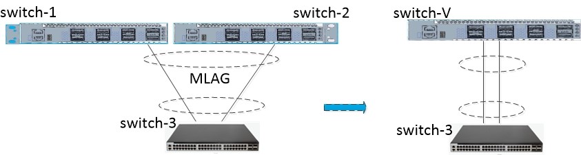
LAG(Multichassis Link Aggregation Group)is a cross-device Link Aggregation. If you can understand the link aggregation of the same device, you can easily understand the cross-device link aggregation. In the following figure, you can imagine switch-1 and Switch-2, connecting one switch(virtual Switch-V) to another switch(switch-3) via aggregation links. Similar to a common aggregation port, M-LAG has advantages such as increase bandwidth, enhance link reliability, and load balance.

The biggest advantage of M-LAG is that it is easy to configure a two-active network system and improve link reliability from the board level to the device level.

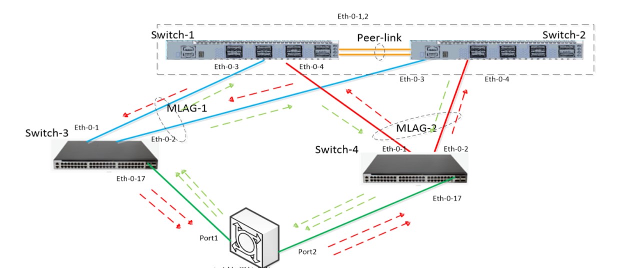
We chose a typical scenario which required high link reliability and load balance in the following figure. Let’s configure MLAG based on this scenario.

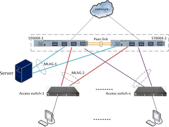
In order to test the performance of the network, we added a professional network testing instrument(IXIA).

The networking topology is as follows:

Enable MLAG

Firstly, to enable the configuration of Switch1 and Switch2. The items include: creating VLAN, creating link aggregation port, config peer-link and peer-ip, ect.   

Verify your configuration:

#################Configuration of switch-1##################

Switch> enable

Switch# configure terminal

Enter configuration commands, one per line.  End with CNTL/Z.

Switch(config)# vlan database

Switch(config-vlan)# vlan 4000

Switch(config-vlan)# exit

Switch(config)# interface range eth-0-1 – 2

Switch(config-if-range)# no shutdown

Switch(config-if-range)# switchport mode trunk

Switch(config-if-range)# switchport trunk allowed vlan add all

Switch(config-if-range)# static-channel-group 40

Switch(config-if-range)# exit

Switch(config)# interface vlan 4000

Switch(config-if)# ip addr 192.168.40.1/24

Switch(config-if)# exit

Switch(config)# interface agg 40

Switch(config-if)# spanning-tree port disable

Switch(config-if)# exit

Switch(config)# mlag configuration

Switch(config-mlag)# peer-link agg 40

Switch(config-mlag)# peer-address 192.168.40.2

Switch(config-mlag)# end

Switch#


#################Configuration of switch-2##################

Switch# configure terminal

Enter configuration commands, one per line.  End with CNTL/Z.

Switch(config)# vlan database

Switch(config-vlan)# vlan 4000

Switch(config-vlan)# exit

Switch(config)# interface range eth-0-1 – 2

Switch(config-if-range)# switchport mode trunk

Switch(config-if-range)# switchport trunk allowed vlan all

Switch(config-if-range)# static-channel-group 40

Switch(config-if-range)# exit

Switch(config)# interface vlan 4000

Switch(config-if)# ip address 192.168.40.2/24

Switch(config-if)# exit

Switch(config)# interface agg 40

Switch(config-if)# spanning-tree port disable

Switch(config-if)# exit

Switch(config)# mlag configuration

Switch(config-mlag)# peer-link agg 40

Switch(config-mlag)# peer-address 192.168.40.1

Switch(config-mlag)# end

Switch#

Check the MLAG Configuration and State

Operation on Switch-1:

Switch# show mlag

MLAG configuration:

—————–

role         : Master

local_sysid  : 34a3.9501.2cb0

remote_sysid : 0000.1a11.1100

mlag_sysid   : 34a3.9501.2cb0

local_syspri : 32768

remote_syspri: 32768

mlag_syspri  : 32768

peer-link    : agg40

peer conf    : Yes

reload-delay : Auto(300s)

Switch#


Operation on Switch-2:

Switch# show mlag

MLAG configuration:

—————–

role         : Slave

local_sysid  : 0000.1a11.1100

remote_sysid : 34a3.9501.2cb0

mlag_sysid   : 34a3.9501.2cb0

local_syspri : 32768

remote_syspri: 32768

mlag_syspri  : 32768

peer-link    : agg40

peer conf    : Yes

reload-delay : Auto(300s)

Switch#

Create MLAG Group

Create a MLAG Group and added port members into the group.

#################Configuration of switch-1##################

Switch# configure terminal

Enter configuration commands, one per line.  End with CNTL/Z.

Switch(config)# vlan database

Switch(config-vlan)# vlan 10

Switch(config-vlan)# exit

Switch(config)# interface eth-0-3

Switch(config-if)# switchport access vlan 10

Switch(config-if)# static-channel-group 10

Switch(config-if)# exit

Switch(config)# interface agg 10

Switch(config-if)# mlag 1

Switch(config)# interface eth-0-4

Switch(config-if)# switchport access vlan 10

Switch(config-if)# static-channel-group 20

Switch(config-if)# exit

Switch(config)# interface agg 20

Switch(config-if)# mlag 2

To repeat the steps and to get the same configuration of switch-2.

Configuration of the peer switches

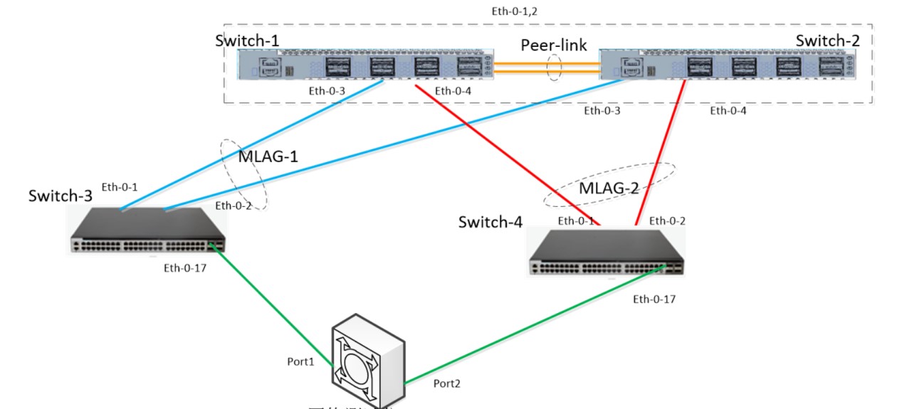
Repeat the third step to configure switch-3 and Switch-4 which are connected to the core as access switches. The configuration is relatively simple. Aggregate the connected physical ports and add them to corresponding VLANs.

Note:  In practice, switch-3 may be a server with multiple network adapters. When the server connects to core switches, switch-1 and Switch-2, through multiple network ports, you need to bind the corresponding network ports on the server to a logical virtual network port. (The bonding modes of network ports on different operating systems vary greatly.)

############Configuration of Switch-3###############

Switch# configure terminal

Enter configuration commands, one per line.  End with CNTL/Z.

Switch(config)# vlan database

Switch(config-vlan)# vlan 10

Switch(config-if-range)# exit

Switch(config)# port-channel 10 load-balance-mode round-robin

Switch(config)# interface range eth-0-1 – 2

Switch(config-if-range)# switchport access vlan 10

Switch(config-if-range)# static-channel-group 10

Switch(config-if-range)# exit

Switch(config)# interface eth-0-17

Switch(config-if)# switchport access vlan 10

Switch(config-if)# flowcontrol send on

Switch(config-if)# end

Switch#

############Configuration of Switch-4###############

Switch# configure terminal

Enter configuration commands, one per line.  End with CNTL/Z.

Switch(config)# vlan database

Switch(config-vlan)# vlan 10

Switch(config-if-range)# exit

Switch(config)# port-channel 20 load-balance-mode round-robin

Switch(config)# interface range eth-0-1 – 2

Switch(config-if-range)# switchport access vlan 10

Switch(config-if-range)# static-channel-group 20

Switch(config-if-range)# exit

Switch(config)# interface eth-0-17

Switch(config-if)# switchport access vlan 10

Switch(config-if)# flowcontrol send on

Switch(config-if)# end

Switch#

Test the service on Tester

After finishing the above configuration, to add a 10G port ETH-0-17 to VLAN10 on switch-3 and Switch-4. The two 10G ports are connected to the 10G port of the test instrument. Each of the two test ports creates 50 streams of 64 bytes length to send to the peer end.

First step, check whether the data is forwarded normally if all switches are working well.
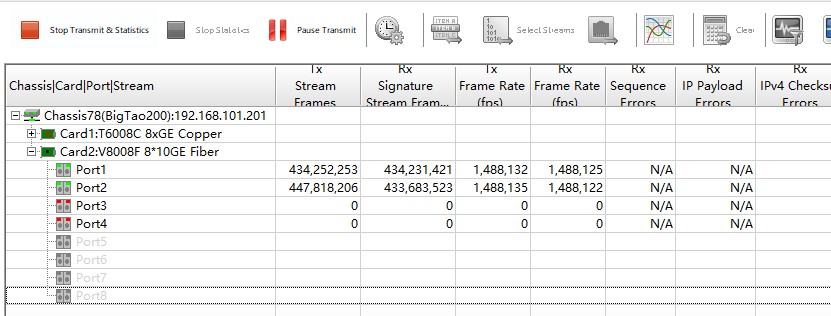
The test result:

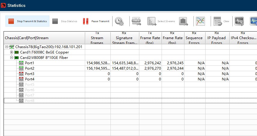
According the result in tester, the transmission bandwidth is 2G, which proves that the expected goal of load balancing is achieved. The data transfer is shown in the figure below:

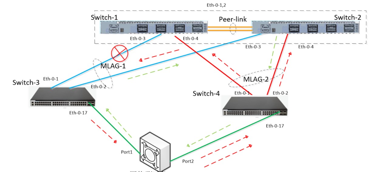
Second Step,Breaking one link of Switch-3

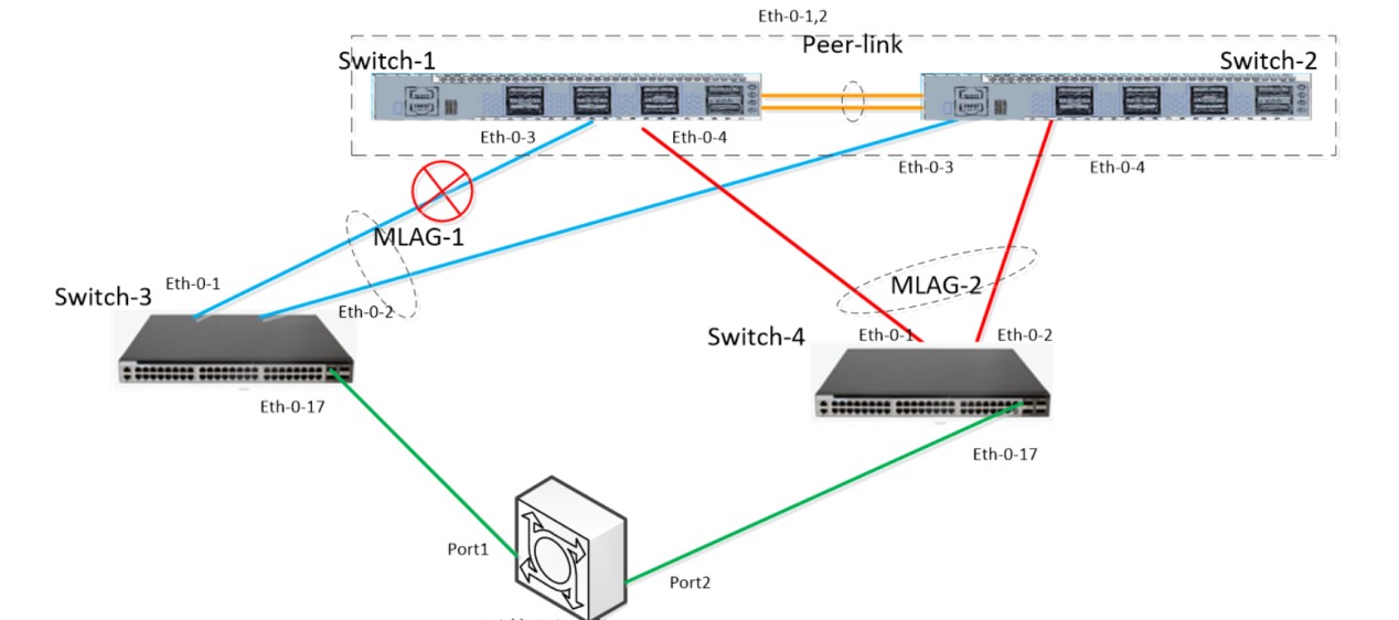
According the result in tester, the forwarding was not terminated by the link breaking. The transmission is continue but reduced by half because only one link available between Core switch and Switch-3.

As expected, the data transfer is shown in the figure below:

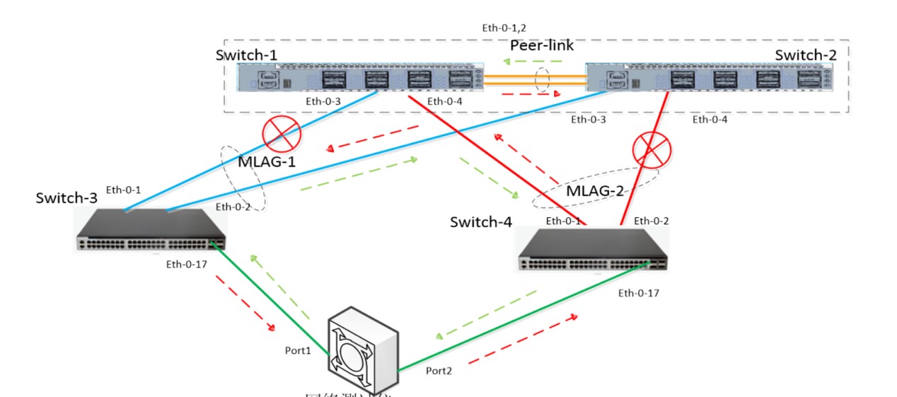
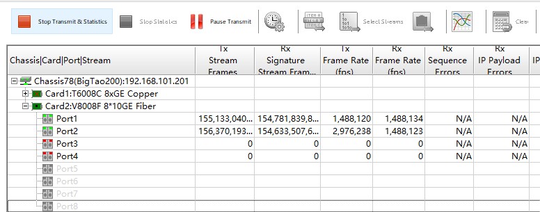
Third Step,breaking one link of Swich-4.  This step is to check if the peer-link working.

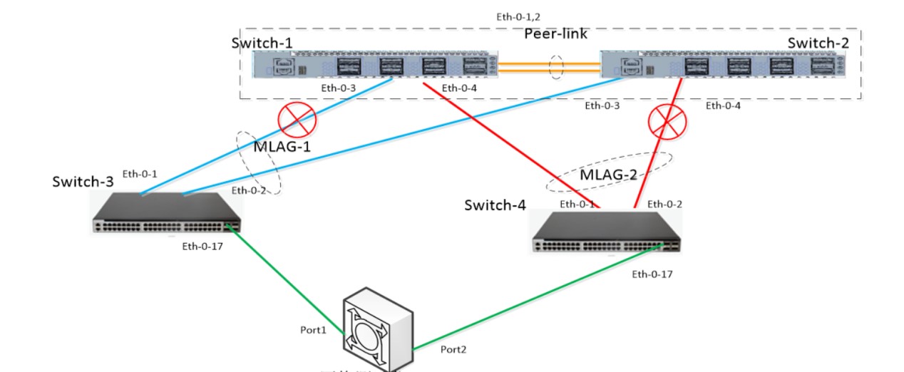
To check the result on Tester:

As expected, the data transfer is shown in the figure below:

Stacking VS M-LAG

Although both stacking and M-LAG improve reliability by virtualizing multiple devices into one device, their configuration vary signification including the dualactive detection (DAD) mode, status negotiation mode, virtual system IP address, and virtual system MAC address. Table1 lists the differences between stacking and M-LAG. Table 1-1 Differences between stacking and M-LAG
Item Stacking M-LAG
Virtual system IP address One IP address is provided for all stack members. After a stack takes effect, each member’s own IP address becomes invalid. M-LAG members have their own IP addresses. No unified IP address is available for all M-LAG members.
Virtual system MAC address One MAC address is provided for all stack members. After a stack takes effect, each member’s own MAC address becomes invalid. M-LAG members have their own MAC addresses. No unified MAC address is available for all M-LAG members.
Device login Logging in to any device in the stack is equivalent to logging in to the master device. All devices are independent of each other, and each device has an independent management port.
DAD link l   DAD in direct mode on service ports l   DAD in relay mode on Eth-Trunk l   DAD through the management port Layer 3 reachable link
Status negotiation Packets are transmitted over the iStack link. Hello packets and packets carrying device information are transmitted over the peer-link.
Detectable faults l   Directly-connected link fault l   Stack member fault l   iStack link fault l   Stack port fault l   Directly-connected link fault l   M-LAG member fault l   Peer-link fault l   Interface fault

Advantages and Disadvantages of Stacking and M-LAG

The configuration of stacking differs greatly from that of M-LAG, and each has its own advantages, as listed in Table1.

Table 1-2 Advantages and disadvantages of stacking and M-LAG

ItemStackingM-LAG
ReliabilityAverage: The control plane is centralized, and faults may be spread on stack members. The failure of the master switch may affect other stack members, and the reliability is low.Relatively high: Control planes are independent and the fault domain is isolated.
CostAverage: Stack cables need to be deployed.Average: Peer-link cables need to be deployed.
Configuration complexitySimple: Multiple devices are configured at the same time and logically virtualized into one device.Average: Multiple devices are configured independently.
ScalabilityAverage: The control plane’s capabilities rely on the master switch.Relatively strong: The scalability is not restricted by a single device.
Impacts on services

Upgrade: Services are interrupted for 20 seconds to 1 minute.

Capacity expansion: When capacity expansion is performed for a stack with three or more devices, the original network architecture needs to be changed or the devices need to be restarted, affecting existing services.

Upgrade: Traffic is interrupted for seconds.

Capacity expansion: The original network architecture is not changed, and the existing services are not affected.

Upgrade complexityHigh: Fast stack upgrade reduces the service interruption time but increases the upgrade operation time and upgrade risk.Low: The upgrade is performed by restarting the device, which is simple and of low risk.
Network designRelatively simple: Single-node design is used logically.Relatively complex: Dual-node design is used logically.

To sum up, stacking is easier to configure and design than M-LAG, but is less flexible, less reliable, and more complex to upgrade. Although more complex to configure, M-LAG has higher reliability than stacking due to decoupling of the control plane and high networking flexibility.