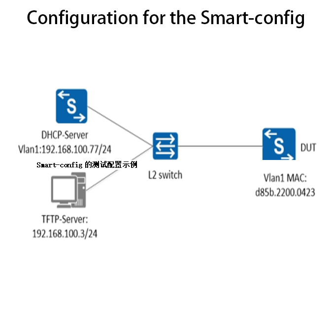
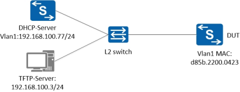
Example of the test configuration for the Smart-config
Smart config Working process of the functions:
- Power up equipment. Determine whether smart config is required: Device enables smart config function (default enabled, configuration command: smartconf initial-switch-deploymen); no startup-config file exists on the device;
- The DHCP server assigns the IP address and carries the TFTP server IP address through the option 150;
- The device finds startup-config and imageon the TFTP server, downloads to local, restart and applies.
operating steps:
1. Complete the physical connection by topology
Build a simple experimental environment as follows. There is no physical connection port in the figure, and any physical port belonging to this vlan is OK. Requirements: a TFTP server, a DHCP server, and a test switch supporting Smart config.
2. Configuring the DHCP-Server
Here we use a switch that supports the DHCP-Server function (or other DHCP-Server servers, including Option150: TFTP-Server IP). These configurations can refer to the user manual for the corresponding series Switch.
The configuration is as follows:
Switch# configure terminal
Switch(config)# service dhcp enable
Switch(config)# dhcp server
Switch(config)# dhcp pool pool100
Switch(config-dhcp)# network 192.168.100.0/24
Switch(config-dhcp)# gateway 192.168.100.77
Switch(config-dhcp)# tftp-server-address 192.168.100.3
Switch(config-dhcp)# exit
Switch(config)# dhcp excluded-address 192.168.100.3
Switch(config)# interface vlan1
Switch(config-if)# ip address 192.168.100.77/24
Switch(config-if)# dhcp server enable
Switch(config-if)# exit
Switch(config)#
3. Prepare the TFTP-Server
Build a TFTP server
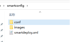
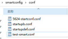
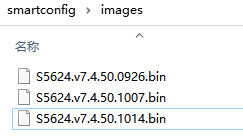
Here, use the application software to open the TFTP service on PC(192.168.100.3), and create the “smartconfig” folder under PC TFTP service directory with the following directory structure (the configuration files in conf directory and the image files in images directory):
Smartconfig/
|–conf/
|–images/
|–smartdeploy.xml
Control image files and configuration files downloaded from the “smartdeploy.xml” file. There are three types of labels in the xml file: MAC, product-id, and SN. Find the image files and configuration files in the of MAC, SN, and product-id. The specific contents are shown as follows:
<SmartDeploy>
<ftype>init</ftype>
<hostprefix>Smart-Switch</hostprefix>
<defItem>
<option>enable</option>
<image>S5624.v7.4.50.0926.bin</image>
<config>startupdef.conf</config>
</defItem>
<groups>
<Item>
<type>MAC</type>
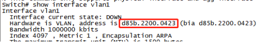
<value>d85b.2200.0423</value>
<image>S5624.v7.4.50.1014.bin</image>
<config>5624-startconf.conf</config>
</Item>
<Item>
<type>productid</type>
<value>09SWITCH-E48-10</value>
<image>productid.bin</image>
<config>productid.cfg</config>
</Item>
<Item>
<type>SN</type>
<value>S5624P-4N1Z-ECD68A8F18AD</value>
<image>wqt.sX624.v7.4.50.1007.bin</image>
<config>startupb.conf</config>
</Item>
</groups>
</SmartDeploy>
Note: In this example,the switch find its own image file (S5624.v7.4.50.1014.bin) and configuration file (5624-startconf.conf) by matching the MAC address (d85b.2200.0423).
Also matched by productid or SN.
If the above match fails, the file specified in <defItem> will be downloaded.
4. Operation on the DUT
- The Smart config function can be “disable”and “enable”, and the default is “enable” without any operation;
- Delete the configuration files beforetesting:
delete flash:/startup-config.conf
delete flash:/boot/startup-config.conf
- Ensure the DUT is properly connected, then power off the switch and then power on (simulate the first use of the switch). After finishing startup, the switch automatically downloads the matching files and then automatically resets.
Note: After one startup, the switch has startup-config.conf file and smart config function fails.